E14R00P06
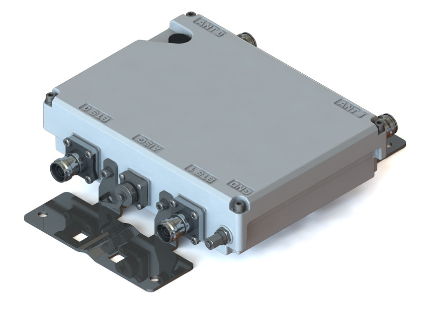
Tower Mounted Amplifier, Dual 2600 MHz with AISG, with 4.3-10 connectors
Features and benefits
- Industry leading PIM performance
- New 4.3-10 connectors for improved PIM performance and size reduction
- TMA is operating in AISG & CWA mode, Alarm Current consumption CWA mode 190 mA
- Designed to boost UP-Link Coverage and KPIs
- RET interface to control antenna RET actuators with AISG standard
- Single AISG with 1 RET connector
- Automatic LNA by-pass function
- Built in lightning protection
- 1 device with 2 sub-units
- Connectors “in line”
- 2 input ports and 2 output ports
Specifications
Product classification
| Product Type | 1-BTS:1-ANT (Uniplex) | Tower mounted amplifier |
General specifications
| Color | Gray |
| Modularity | 2-Twin |
| Mounting | Pole | Wall |
| Mounting Pipe Hardware | Band clamps (2) |
| RF Connector Interface | 4.3-10 Female |
| RF Connector Interface Body Style | Long neck |
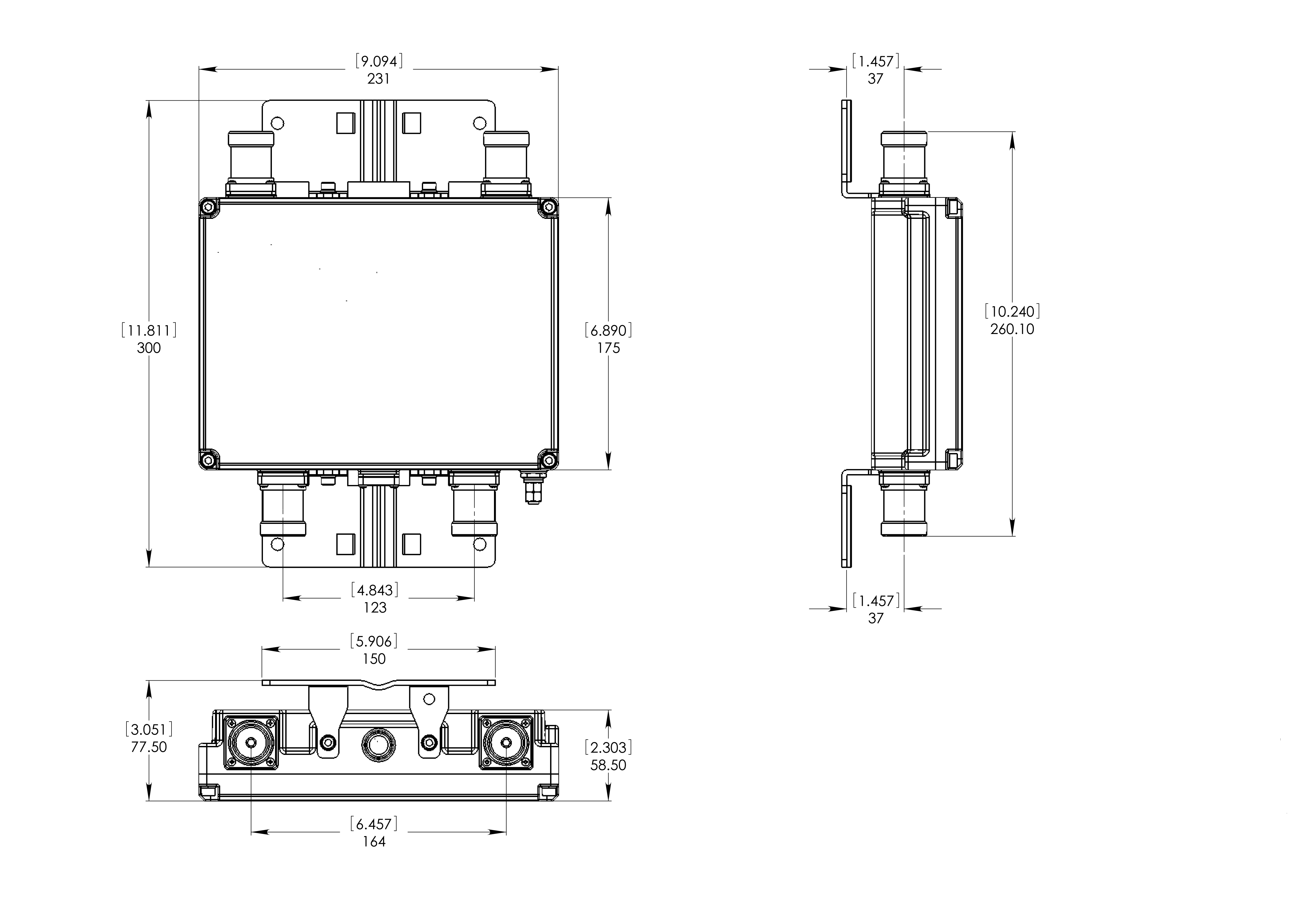
Dimensions
| Height | 175 mm | 6.89 in |
| Width | 231 mm | 9.094 in |
| Depth | 58.5 mm | 2.303 in |
| Ground Screw Diameter | 8 mm | 0.315 in |
| Mounting Pipe Diameter Range | 40–160 mm |
Outline drawing
| Click on image to enlarge. |
Electrical specifications
| License Band, LNA | IMT 2600 |
Electrical specifications, dc power/alarm
| dc Switching/Redundancy | Yes |
| Lightning Surge Current | 10 kA |
| Lightning Surge Current Waveform | 8/20 waveform |
| Operating Current at Voltage | 100 mA @ 12 V |
| Operating Current Tolerance | ±15 mA |
| Voltage | 7–30 Vdc |
| Alarm Current, CWA Mode | 185 mA ±10 mA |
Electrical specifications, aisg
| AISG Connector | 8-pin DIN Female |
| AISG Connector Standard | IEC 60130-9 |
| Protocol | AISG 2.0 |
| Voltage, AISG Mode | 10–30 Vdc |
Electrical specifications
| Sub-module | 1 | 2 |
| Branch | 1 |
| Port Designation | ANT |
| License Band | IMT 2600, LNA |
Electrical specifications, rx uplink
| Frequency Range, MHz | 2500–2570 |
| Bandwidth, MHz | 70.00 |
| Gain, nominal, dB | 12.0 |
| Gain Tolerance, dB | ±1 |
| Noise Figure, maximum, dB | 1.6 |
| Noise Figure, typical, dB | 1.5 |
| Group Delay Variation, maximum, ns | 20 |
| Group Delay Variation Bandwidth, MHz | 5.00 |
| Output IP3, minimum, dBm | 25 |
| Return Loss, minimum, dB | 18 |
| Insertion Loss - Bypass Mode, typical, dB | 2.5 |
| Return Loss - Bypass Mode, typical, dB | 16 |
| TX Band Rejection, minimum, dB | 45 |
Electrical specifications, tx downlink
| Frequency Range, MHz | 2620–2690 |
| Bandwidth, MHz | 70.00 |
| Insertion Loss, maximum, dB | 0.50 |
| Insertion Loss, typical, dB | 0.30 |
| Insertion Loss Ripple, maximum, dB | 0.10 |
| Group Delay Variation, maximum, ns | 10 |
| Group Delay Variation Bandwidth, MHz | 5.00 |
| Return Loss, minimum, dB | 18 |
| Input Power, RMS, maximum, W | 160 |
| Input Power, PEP, maximum, W | 2,500 |
| 3rd Order PIM, typical, dBc | -160 |
| 3rd Order PIM Test Method | Two +43 dBm carriers |
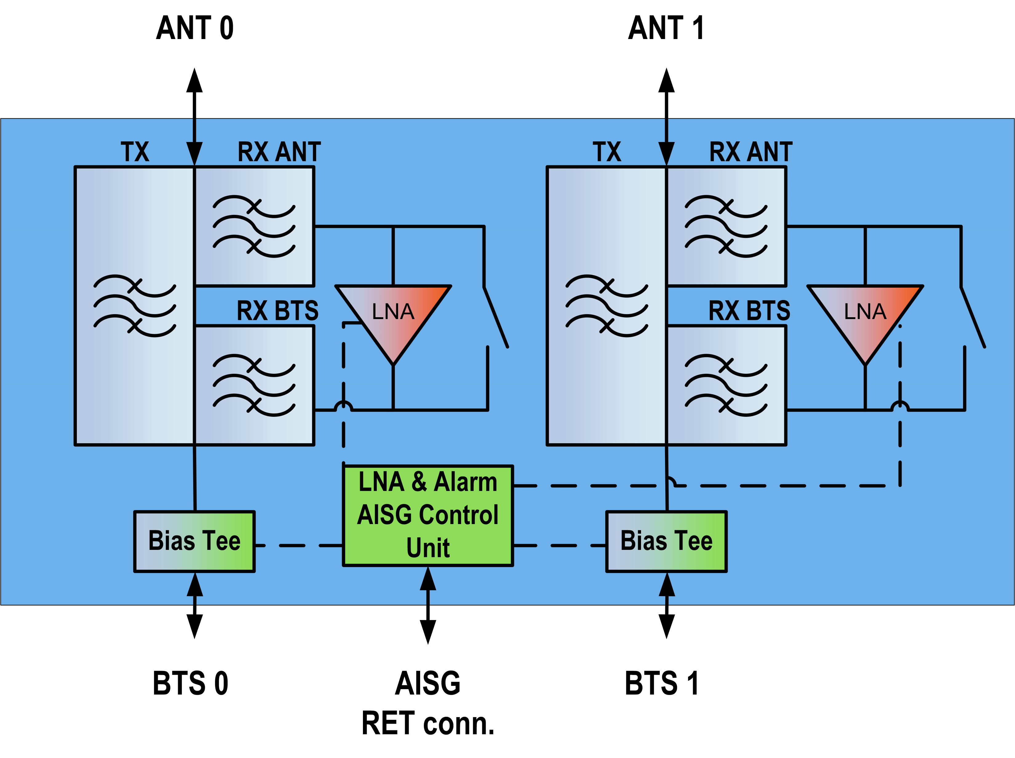
Block diagram
| Click on image to enlarge. |
Material specifications
| Finish | Painted |
Mechanical specifications
| Wind Speed, maximum | 198 km/h (123 mph) |
Environmental specifications
| Operating Temperature | -40 °C to +65 °C (-40 °F to +149 °F) |
| Relative Humidity | Up to 100% |
| Corrosion Test Method | IEC 60068-2-11, 30 days |
| Ingress Protection Test Method | IEC 60529:2001, IP67 |
Packaging and weights
| Included | Mounting hardware |
| Volume | 2.3 L |
| Weight, net | 4 kg | 8.818 lb |
Product classification
| Product Type | 1-BTS:1-ANT (Uniplex) | Tower mounted amplifier |
General specifications
| Color | Gray |
| Modularity | 2-Twin |
| Mounting | Pole | Wall |
| Mounting Pipe Hardware | Band clamps (2) |
| RF Connector Interface | 4.3-10 Female |
| RF Connector Interface Body Style | Long neck |
Dimensions
| Height | 175 mm | 6.89 in |
| Width | 231 mm | 9.094 in |
| Depth | 58.5 mm | 2.303 in |
| Ground Screw Diameter | 8 mm | 0.315 in |
| Mounting Pipe Diameter Range | 40–160 mm |
Electrical specifications
| License Band, LNA | IMT 2600 |
Electrical specifications, dc power/alarm
| dc Switching/Redundancy | Yes |
| Lightning Surge Current | 10 kA |
| Lightning Surge Current Waveform | 8/20 waveform |
| Operating Current at Voltage | 100 mA @ 12 V |
| Operating Current Tolerance | ±15 mA |
| Voltage | 7–30 Vdc |
| Alarm Current, CWA Mode | 185 mA ±10 mA |
Electrical specifications, aisg
| AISG Connector | 8-pin DIN Female |
| AISG Connector Standard | IEC 60130-9 |
| Protocol | AISG 2.0 |
| Voltage, AISG Mode | 10–30 Vdc |
Electrical specifications
| Sub-module | 1 | 2 |
| Branch | 1 |
| Port Designation | ANT |
| License Band | IMT 2600, LNA |
Electrical specifications, rx uplink
| Frequency Range, MHz | 2500–2570 |
| Bandwidth, MHz | 70.00 |
| Gain, nominal, dB | 12.0 |
| Gain Tolerance, dB | ±1 |
| Noise Figure, maximum, dB | 1.6 |
| Noise Figure, typical, dB | 1.5 |
| Group Delay Variation, maximum, ns | 20 |
| Group Delay Variation Bandwidth, MHz | 5.00 |
| Output IP3, minimum, dBm | 25 |
| Return Loss, minimum, dB | 18 |
| Insertion Loss - Bypass Mode, typical, dB | 2.5 |
| Return Loss - Bypass Mode, typical, dB | 16 |
| TX Band Rejection, minimum, dB | 45 |
Electrical specifications, tx downlink
| Frequency Range, MHz | 2620–2690 |
| Bandwidth, MHz | 70.00 |
| Insertion Loss, maximum, dB | 0.50 |
| Insertion Loss, typical, dB | 0.30 |
| Insertion Loss Ripple, maximum, dB | 0.10 |
| Group Delay Variation, maximum, ns | 10 |
| Group Delay Variation Bandwidth, MHz | 5.00 |
| Return Loss, minimum, dB | 18 |
| Input Power, RMS, maximum, W | 160 |
| Input Power, PEP, maximum, W | 2,500 |
| 3rd Order PIM, typical, dBc | -160 |
| 3rd Order PIM Test Method | Two +43 dBm carriers |
Material specifications
| Finish | Painted |
Mechanical specifications
| Wind Speed, maximum | 198 km/h (123 mph) |
Environmental specifications
| Operating Temperature | -40 °C to +65 °C (-40 °F to +149 °F) |
| Relative Humidity | Up to 100% |
| Corrosion Test Method | IEC 60068-2-11, 30 days |
| Ingress Protection Test Method | IEC 60529:2001, IP67 |
Packaging and weights
| Included | Mounting hardware |
| Volume | 2.3 L |
| Weight, net | 4 kg | 8.818 lb |
| Click on image to enlarge. |
| Click on image to enlarge. |
Installation & videos
Filter Products – Designed for PIM Excellence

Filter Products – Designed for PIM Excellence
Documentation & downloads