TMAT192123B68-21 | E14R00P31
Tower Mounted Amplifier,Twin Diplexed PCS/AWS/WCS,617–894 MHz bypass 4.3-10
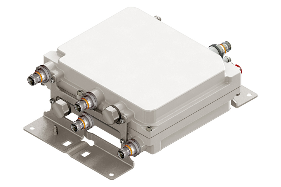
Features and benefits
- New Triple-band TMA for PCS, AWS 1-4 and WCS in a compact twin form factor
- Low frequency bypass of 617-894 MHz covers Band 14 public safety operating frequencies
- Significantly reduces complexity of tower top architectures
- Also available in a quad configuration to support 4 x 4 requirements
- New 4.3-10 connectors for improved PIM performance and size reduction
- Support DC/AISG antenna Auto-forward
Specifications
Product classification
| Product Type | 1-BTS:2-ANT (Diplex) | Tower mounted amplifier |
General specifications
| Color | Gray |
| Modularity | 2-Twin |
| Mounting | Pole | Wall |
| Mounting Pipe Hardware | Band clamps (2) |
| RF Connector Interface | 4.3-10 Female |
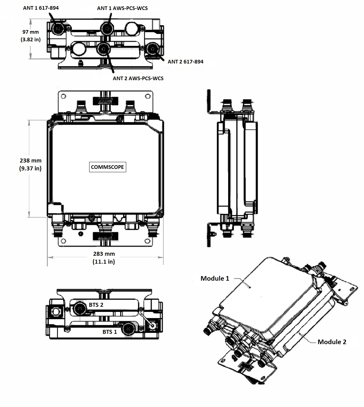
Dimensions
| Height | 283 mm | 11.142 in |
| Width | 238 mm | 9.37 in |
| Depth | 97 mm | 3.819 in |
| Ground Screw Diameter | 6 mm | 0.236 in |
| Mounting Pipe Diameter Range | 40–160 mm |
Outline drawing
| Click on image to enlarge. |
Electrical specifications
| License Band, Band Pass | APT 700 | CEL 850 | EDD 800 | LMR 750 | LMR 800 | USA 700 | USA 750 |
| License Band, LNA | AWS 1700 | PCS 1900 | WCS 2300 |
Electrical specifications, dc power/alarm
| dc Switching/Redundancy | Yes |
| Lightning Surge Current | 10 kA |
| Lightning Surge Current Waveform | 8/20 waveform |
| Operating Current at Voltage | 160mA @ 24V |
| Voltage | 7–30 Vdc |
Electrical specifications, aisg
| AISG Carrier | 2.176 MHz ± 100 ppm |
| AISG Connector | 8-pin DIN Female |
| AISG Connector Standard | IEC 60130-9 |
| Protocol | AISG 2.0 |
| Voltage, AISG Mode | 10–30 Vdc |
Electrical specifications
| Sub-module | 1 | 2 | 1 | 2 | 1 | 2 | 1 | 2 |
| Branch | 1 | 2 | 2 | 2 |
| Port Designation | 617–894 | AWS–PCS | AWS-PCS | WCS |
| AISG 2.0 Device Subunit | E14R00P31 2/5 | E14R00P31 3/6 | E14R00P31 1/4 | |
| License Band | CEL 850, Band Pass USA 750, Band Pass | AWS 1700, LNA | PCS 1900, LNA | WCS 2300, LNA |
Electrical specifications, band pass
| Frequency Range, MHz | 617–894 | |||
| Insertion Loss, typical, dB | 0.10 | |||
| Total Group Delay, typical, ns | 4 | |||
| Return Loss, typical, dB | 22 | |||
| Input Power, RMS, maximum, W | 200 | |||
| Input Power, PEP, maximum, W | 2,000 | |||
| 3rd Order PIM, typical, dBc | -155 | |||
| 3rd Order PIM Test Method | 2 x 20 W CW tones |
Electrical specifications, rx uplink
| Frequency Range, MHz | 1695–1780 | 1850–1910 | 2305–2315 | |
| Bandwidth, MHz | 85.00 | 60.00 | 10.00 | |
| Gain, nominal, dB | 12.5 | 12.5 | 13.0 | |
| Gain Tolerance, dB | ±1.5 | ±1.5 | ±1.0 | |
| Noise Figure, typical, dB | 1.1 | 1.3 | 1.8 | |
| Total Group Delay, maximum, ns | 50 | 150 | 130 | |
| Return Loss, typical, dB | 20 | 22 | 22 | |
| Insertion Loss - Bypass Mode, typical, dB | 1.4 | 2.3 | 2.8 | |
| Return Loss - Bypass Mode, typical, dB | 18 | 18 | 18 |
Electrical specifications, tx downlink
| Frequency Range, MHz | 2110–2200 | 1930–1990 | 2350–2360 | |
| Bandwidth, MHz | 90.00 | 60.00 | 10.00 | |
| Insertion Loss, typical, dB | 0.30 | 0.50 | 0.60 | |
| Total Group Delay, maximum, ns | 20 | 50 | 50 | |
| Return Loss, typical, dB | 20 | 22 | 22 | |
| Input Power, RMS, maximum, W | 200 | 200 | 150 | |
| Input Power, PEP, maximum, W | 2,000 | 2,000 | 1,500 | |
| 3rd Order PIM, typical, dBc | -155 | -155 | ||
| 3rd Order PIM Test Method | 1 x 20 W AWS CW tone 1 x 20 W PCS CW tone | 2 x 20 W CW tones | ||
| Higher Order PIM, typical, dBc | -155 | |||
| Higher Order PIM Test Method | 2 x 20 W CW tones |
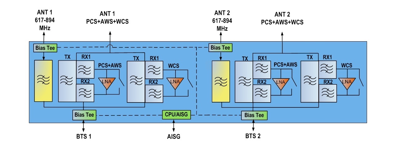
Block diagram
| Click on image to enlarge. |
Material specifications
| Finish | Painted |
Environmental specifications
| Operating Temperature | -40 °C to +65 °C (-40 °F to +149 °F) |
| Relative Humidity | Up to 100% |
| Corrosion Test Method | IEC 60068-2-11, 30 days |
| Ingress Protection Test Method | IEC 60529:2001, IP67 |
Packaging and weights
| Included | Mounting hardware |
| Mounting Hardware Weight | 1 kg | 2.205 lb |
| Weight, without mounting hardware | 9.4 kg | 20.723 lb |
Regulatory compliance/certifications
| Agency | Classification |
|
CHINA-ROHS
|
Above maximum concentration value |
| ROHS | Compliant/Exempted |
| UK-ROHS | Compliant/Exempted |
Product classification
| Product Type | 1-BTS:2-ANT (Diplex) | Tower mounted amplifier |
General specifications
| Color | Gray |
| Modularity | 2-Twin |
| Mounting | Pole | Wall |
| Mounting Pipe Hardware | Band clamps (2) |
| RF Connector Interface | 4.3-10 Female |
Dimensions
| Height | 283 mm | 11.142 in |
| Width | 238 mm | 9.37 in |
| Depth | 97 mm | 3.819 in |
| Ground Screw Diameter | 6 mm | 0.236 in |
| Mounting Pipe Diameter Range | 40–160 mm |
Electrical specifications
| License Band, Band Pass | APT 700 | CEL 850 | EDD 800 | LMR 750 | LMR 800 | USA 700 | USA 750 |
| License Band, LNA | AWS 1700 | PCS 1900 | WCS 2300 |
Electrical specifications, dc power/alarm
| dc Switching/Redundancy | Yes |
| Lightning Surge Current | 10 kA |
| Lightning Surge Current Waveform | 8/20 waveform |
| Operating Current at Voltage | 160mA @ 24V |
| Voltage | 7–30 Vdc |
Electrical specifications, aisg
| AISG Carrier | 2.176 MHz ± 100 ppm |
| AISG Connector | 8-pin DIN Female |
| AISG Connector Standard | IEC 60130-9 |
| Protocol | AISG 2.0 |
| Voltage, AISG Mode | 10–30 Vdc |
Electrical specifications
| Sub-module | 1 | 2 | 1 | 2 | 1 | 2 | 1 | 2 |
| Branch | 1 | 2 | 2 | 2 |
| Port Designation | 617–894 | AWS–PCS | AWS-PCS | WCS |
| AISG 2.0 Device Subunit | E14R00P31 2/5 | E14R00P31 3/6 | E14R00P31 1/4 | |
| License Band | CEL 850, Band Pass; USA 750, Band Pass | AWS 1700, LNA | PCS 1900, LNA | WCS 2300, LNA |
Electrical specifications, band pass
| Frequency Range, MHz | 617–894 | |||
| Insertion Loss, typical, dB | 0.10 | |||
| Total Group Delay, typical, ns | 4 | |||
| Return Loss, typical, dB | 22 | |||
| Input Power, RMS, maximum, W | 200 | |||
| Input Power, PEP, maximum, W | 2,000 | |||
| 3rd Order PIM, typical, dBc | -155 | |||
| 3rd Order PIM Test Method | 2 x 20 W CW tones |
Electrical specifications, rx uplink
| Frequency Range, MHz | 1695–1780 | 1850–1910 | 2305–2315 | |
| Bandwidth, MHz | 85.00 | 60.00 | 10.00 | |
| Gain, nominal, dB | 12.5 | 12.5 | 13.0 | |
| Gain Tolerance, dB | ±1.5 | ±1.5 | ±1.0 | |
| Noise Figure, typical, dB | 1.1 | 1.3 | 1.8 | |
| Total Group Delay, maximum, ns | 50 | 150 | 130 | |
| Return Loss, typical, dB | 20 | 22 | 22 | |
| Insertion Loss - Bypass Mode, typical, dB | 1.4 | 2.3 | 2.8 | |
| Return Loss - Bypass Mode, typical, dB | 18 | 18 | 18 |
Electrical specifications, tx downlink
| Frequency Range, MHz | 2110–2200 | 1930–1990 | 2350–2360 | |
| Bandwidth, MHz | 90.00 | 60.00 | 10.00 | |
| Insertion Loss, typical, dB | 0.30 | 0.50 | 0.60 | |
| Total Group Delay, maximum, ns | 20 | 50 | 50 | |
| Return Loss, typical, dB | 20 | 22 | 22 | |
| Input Power, RMS, maximum, W | 200 | 200 | 150 | |
| Input Power, PEP, maximum, W | 2,000 | 2,000 | 1,500 | |
| 3rd Order PIM, typical, dBc | -155 | -155 | ||
| 3rd Order PIM Test Method | 1 x 20 W AWS CW tone; 1 x 20 W PCS CW tone | 2 x 20 W CW tones | ||
| Higher Order PIM, typical, dBc | -155 | |||
| Higher Order PIM Test Method | 2 x 20 W CW tones |
Material specifications
| Finish | Painted |
Environmental specifications
| Operating Temperature | -40 °C to +65 °C (-40 °F to +149 °F) |
| Relative Humidity | Up to 100% |
| Corrosion Test Method | IEC 60068-2-11, 30 days |
| Ingress Protection Test Method | IEC 60529:2001, IP67 |
Packaging and weights
| Included | Mounting hardware |
| Mounting Hardware Weight | 1 kg | 2.205 lb |
| Weight, without mounting hardware | 9.4 kg | 20.723 lb |
| Click on image to enlarge. |
| Click on image to enlarge. |
Regulatory compliance/certifications
| Agency | Classification |
|
CHINA-ROHS
|
Above maximum concentration value |
| ROHS | Compliant/Exempted |
| UK-ROHS | Compliant/Exempted |
Installation & videos
Installation instruction
Filter Products – Designed for PIM Excellence

Filter Products – Designed for PIM Excellence
Documentation & downloads